Back to: Build a 6502 based computer
I would like my computer to be able to display text and images on a monitor. Therefore, I will design and build a video card, which will connect between the computer and a monitor.
The video card needs a number of different stages. The first stage to consider is an interface, an output interface will connect the card to the monitor. For this interface I need to decide what connection and standard to implement.
Over the years there have been many standards of output interfaces. The ones that I am interested in are CGA, EGA, VGA and SVGA. Of these, VGA (Video Graphics Array), which was introduced with the IBM PS/2, in 1987, became ubiquitous and is the one that I wish to implement. I chose this because many devices currently in use (monitors, TVs, projectors) still have VGA connections and it is era-appropriate. Also, it would be possible to interface with other output interfaces, including BNC and DVI! BNC will work because it is just a breakout of the connections that I will be using in the VGA standard. DVI is a digital standard but is workable because it is compatible with analogue signals, via a mode called DVI-A.
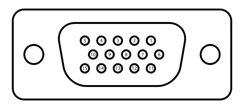
Figure 1 shows a VGA connection. The VGA connector is a 15-pin D-subminiature, with 3 rows – their functions are listed in table 1. It is often known as a DE15 connector.
When VGA is being discussed it is common to see the connector described as DB15. However, this is incorrect. Even in professional publications you can find it described as DB15! However, DB15 and DE15 are different connectors. They both have 15 pins, but the casings are different sizes. DB15 has the pins arranged as a row of 7 and a row of 8. DE15 has the pins arranged as 3 rows of 5. The D describes the shape of the connector and the B and E descibe the size.
VGA signals are analogue but the video card will be digital. Therefore, another stage that I need to design is a circuit that converts the digital signals that I generate to analogue signals that a monitor requires when it receives a VGA signal. To achieve this I will use a type of circuit known as a digital-to-analogue converter (DAC).
| 1 | RED |
| 2 | GREEN |
| 3 | BLUE |
| 4 | ID2/RES |
| 5 | GND |
| 6 | RED_RTN |
| 7 | GREEN_RTN |
| 8 | BLUE_RTN |
| 9 | KEY/PWR |
| 10 | GND |
| 11 | ID0/RES |
| 12 | ID1/SDA |
| 13 | HSync |
| 14 | VSync |
| 15 | ID3/SCl |
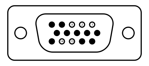
Although there are 15 connections, I will be using 10 of these, as shown in figure 2 and table 2. These are red, green, blue, horizontal sync and vertical sync, plus five ground connections.
| 1 | RED |
| 2 | GREEN |
| 3 | BLUE |
| 13 | HSync |
| 14 | VSync |
The implementation that I would like to aim for is a video card that satisfies the requirements of the original VGA specification, which are in table 3.
| screen refresh rate | 60 Hz | |
| vertical refresh | 31.46875 kHz | |
| pixel frequency | 25.175 MHz | |
| HORIZONTAL | TIME (µs) | |
| visible area | 640 | 25.422045680238 |
| front porch | 16 | 0.63555114200596 |
| sync pulse | 96 | 3.8133068520357 |
| back porch | 48 | 1.9066534260179 |
| whole line | 800 | 31.777557100298 |
| VERTICAL | TIME (ms) | |
| visible area | 480 | 15.253227408143 |
| front porch | 10 | 0.31777557100298 |
| sync pulse | 2 | 0.063555114200596 |
| back porch | 33 | 1.0486593843098 |
| whole frame | 525 | 16.683217477656 |
Some problems will need to be overcome to be able to implement VGA. The first is the VGA signal timing. To keep each frame in time, there is a signal timing that needs to be adhered to. What signal timing is required is dependent on the resolution and refresh rate and in turn, it is a function of the pixel frequency. The required pixel frequency is 25.175 MHz. There are a number of ways of generating this, I will use a crystal oscillator.
I need to design a circuit that takes the 25.175 MHz pixel frequency and uses it to generate a horizontal sync and a horizontal blanking pulse.
I need to design a circuit that takes the 25.175 MHz pixel frequency and uses it to generate a vertical sync and a vertical blanking pulse.
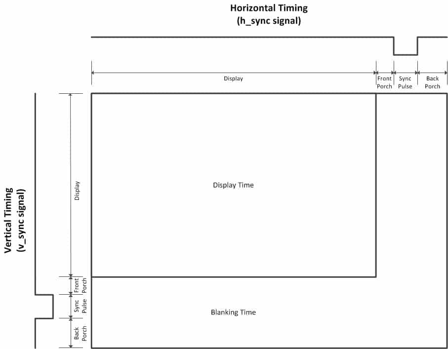
Figure 3 shows the anatomy of a frame. Each frame is created by starting in the top-left corner and moving to the right. When one line is complete, the next line begins, progressing from left to right. When all of the lines have been drawn, one frame is complete. The process then repeats. As well as the visual information, there is information that corresponds to horizontal and vertical timing. These are necessary to ensure that the image is drawn at the correct point! These timing signals can be broken down into a front porch, sync pulse and back porch
The front porch occurs after the line of video information has ended and blanks the signal, ready for the sync pulse that follows. The back porch occurs after the sync pulse and gives time for the beam (of a CRT) to move from right to left, ready for the next line. There is no beam with an LCD monitor but the timing still needs to be followed to keep the timings correct. These pulses also apply to vertical timing. However, the back porch for the vertical signal is also needed for the beam to return not just from right to left but also to the top!
Looking at table 3 we can see that each line needs to be 800 pixels and last 31.777557100298 µs. To design a circuit to meet this criterion, it must know when 31.777557100298 µs has elapsed and then reset to 0. There are a lot of ways of achieving this but in any scenario, I need to create some form of counting circuit. 640 in binary is 1010000000, which is a 10-bit number. What I will do is use three 4-bit counters and cascade them so that they form a 10-bit counter.
The other criterion is that the circuit is synchronous. We can split counters into two categories. asynchronous and synchronous. With an asynchronous counter, a clock is provided at the first stage and ripples through to the following stage(s). With a synchronous counter, a clock is provided to each stage, making everything clock in time. I need to use a synchronous counter to keep everything in time.
To build my counter circuit, I will use three 74161s. These can be chained together and they are synchronous counters. I will tie all of their clock pins together, making each count together. Since the 74161 is a 4-bit counter, it can count to 15. With the three cascaded together, the circuit will create a 12-bit counter, allowing me to count up to 4096! I will also tie all of the clear pins together, so that all of the counters are reset to 0 at the same time. To detect when I have reached the required numbers, I will connect the relevant outputs of the counters to logic gates to get the required combination.
HORIZONTAL

800
I have a counter that counts from 0 to 4096. Now I need to modify it to count to 800 and then reset it to 0. I will use logic gates to detect when 800 has been reached. In binary, 800 is 1100100000. If I connected a 10-input AND gate to the outputs of the counter and an inverter at the input of the 1st, 2nd, 3rd, 4th, 5th, 7th AND 8th bit, the AND gate will have a 1 at its output when it has counted to 1100100000. This will work but can be improved on with some optimisations. I could reduce this to just a 3-input AND gate! This is possible because I only need to know when the 6th, 9th and 10th bits are 1. Any 1s at the 1st, 2nd, 3rd, 4th, 5th, 7th and 8th bit are irrelevant because the counter will never count that high! I could then connect the output to the clear pins of the 74161s. However, the clear pin is active low, so I would need to invert the output. However, another solution is to use a NAND gate to replace the separate AND and NOT gates. I will use a 7410, which contains three 3-input NAND gates. Now, when 800 is reached the three inputs of the NAND gate will be 1 and the output will be 0, causing the counter to reset to 0.
It would be good to check if the timing is correct. One way to do this is with a logic analyser. If you look at Figure 5 you will see the results. This shows that the scan line that I have generated is 26.42µs. I need 31.777557100298 µs, which will be close enough.

Now that I have a counter that can count to 800 and then reset to 0, I need circuitry to detect when the front porch, sync pulse and back porch have been reached. I will use the same method of using NAND gates to achieve this.
640
Now I need to add logic to detect when the counter has reached 640. 640 in binary is 1010000000. Using the same method as I did to detect when 800 had been reached, I need to detect when the 8th AND 10th bit has changed to a 1. As before, I will only check for the bits that need to be 1. Therefore, I can use a 2-input NAND gate to check the 8th and 10th bit. 25.422045680238 µs.
656
Now I need to add logic to detect when the counter has reached the start of the horizontal sync pulse, which is 656 (640 + 16). The reason for this is that I need to know when the visible area has ended and the blanking period has started. 656 in binary is 1010010000. I need to detect when the 5th, 8th AND 10th bits have changed to a 1. The 7410 contains three 3-input NAND gates, so I can use one of these. 0.63555114200596 µs.
752
Now I need to add logic to detect when the counter has reached the end of the vertical sync pulse, which is 752 (656 + 96). 752 in binary is 1011110000. Therefore, I need to detect when the 5th, 6th, 7th, 8th AND 10th bits have changed to a 1. In the 74 series there is no 5-input NAND gate. There is however the 7430, which contains a single 8-input NAND gate. There will be three unused pins. If these are tied high, it will act as a 5-input NAND gate! 1.9066534260179 µs.
VERTICAL

I will build two counters, one that counts the pixels horizontally and one that counts the pixels vertically. To count the pixels I will use a 74161. I need it to count up to 264, which will require 9 bits. The 74161 is a 4-bit counter, so I will need 3 of them.
The clear pin will reset the counters to 0. I will need them all to clear at the same time, so I will tie them together. All of the counters will use the same clock, so I will tie all of the clock pins together.
I won’t be using the data inputs because I won’t be loading any data into this. The 74161s will be used purely as counters. I will connect all of the enable pins high, as I want the chips to always be enabled. Because I will not be using the data inputs, I will not need to use the load pins. The load pins are active low, so I will tie all of them high. The enable T is what is used for the ripple carry. So I will use the first one, so that the 4 bits in the first counter roll over to the second counter and then to the third. The ripple carry output of the 1st is connected to the enable of the second. Then the ripple carry of the second chip to the enable of the third chip. This creates a cascade, so I can count 12 bits, although I only care about the first 9 bits. I should now have a 12-bit ripple counter. To check that it is working as intended, I will connect it to 12 LEDs. I can’t connect the clock signal from the computer because that would be too fast to see anything happening. I will use my 555 timer circuit to provide the clock signal. It’s counting in binary, which is what I want.
We want to start at 0 and know when we have reached 200, 210, 242 and 264. Then I want to reset back to 0.
image
The pixel data needs to be stored somewhere in memory. I will store images in an eeprom. eeprom can give the byte stored at the address according to the x and y positions. The byte can represent the pixel data. VGA expects a voltage between 0 and 0.7 V. This range controls the intensity of each colour. I will connect each output from the counters to the address bus of the eeprom. The data bus will be connected to the inputs to the VGA connector. I will use 6 lines of the data bus, 2 for each colour. The horizontal sync signals generated from the counter circuitry will be connected to their corresponding VGA connections. This is called a frame buffer, it’s where the image is stored.
interface
Now that I have a working video card, I want to connect it to the computer, so I can run programs and load pictures that output to it. I plan to remove the eeprom that I used for testing and use the eeprom in the computer to store programs and pictures. I will then use the RAM in the computer to load these.
bus contention
For this to work, I need a way of isolating the video card from the computer when the CPU is accessing the RAM. The reason for this is that if I did not do this, then whatever is being outputted to the RAM would cause ‘garbage’ to be displayed! Without any intervention there would be times when both the video card and the CPU are trying to access the RAM. This is bad, as anything that the CPU is putting onto the buses would be read by the video card and could cause garbage to be displayed, since the video card would think that it’s pixel data! This is known as bus contention. What I need to do is to design a circuit that only allows either the CPU or the video card to access the RAM at any point in time. There are a number of possible solutions, I plan on designing a circuit that implements a technique known as Direct Memory Access (DMA). DMA is a way of allowing a connection to be made to the RAM, without the involvement of the CPU. This means that only visual data will be outputted and also allows the CPU to do work at the same time.
To implement DMA I will use a bus transceiver. A transceiver allows two-way communication between two buses. This will prevent the 6502 and the video card from affecting each other when they use the buses. Transceiver is a portmanteau of transmitter and receiver. Also, the transceiver that I will use is a tri-state transceiver. This means that the output can be logic 0, logic 1 or high-impedance. In the high-impedance state, the bus will be disconnected. This way I can ensure that either the 6502 or the video card is using the buses and the other is disconnected from the buses. I will use a 74245, which is an octal bus transceiver. The 74245 contains a direction pin, which is used to control the direction of data. Octal means 8, which means that I will need 3, as I need to connect the data bus (which is 8 bits wide) and the address bus (which is 16 bits wide). There is also an enable pin, which I will use to isolate the circuits. Using these 2 pins I can control the connections between the video card and the RAM. This is called bus mastering – controlling which bus has control. The plan is to give the video card control during the period that a frame is drawn and to give the CPU control during blanking periods.
In addition to controlling when the graphics card has access to the RAM, I need to be able to stop the CPU from running when it should not be accessing the RAM. The 6502 has 2 pins that I can use to implement this: RDY and BE. RDY is the ready pin. BE is the bus enable pin.
The plan is to allow the graphics card to use RAM, stop the CPU from carrying out instructions and to stop the CPU from using the data and address buses during display time. During the blanking period the CPU will continue as normal.
The BE pin only exists on the CMOS 6502, not the NMOS version! This is another good reason to use the CMOS version. The BE (bus enable) pin allows external control of the buses.
The RDY (ready) pin can be used for a number of operations, here I wish to use it to connect to my DMA controller. When this pin is high the processor runs, when it is low it halts the processor (in its current state).
It is the use of the combination of the BE and RDY pins that will allow me to implement DMA as it will force the 6502 to give up control of the buses. I will design circuitry that will be able to make the RDY pin go low, forcing the 6502 to halt at its current state. The circuitry will also be able to make the BE pin go low, putting all of the 6502’s output lines into a high-impedance state – meaning that it cannot have any effect on the address and data lines (and some other pins).
DAC
What needs to be done is to take the output from the EEPROM, which is digital and transform it into what a monitor requires, which is analogue. What is needed is a Digital to Analogue Converter (DAC). The type of DAC that I will use is an R2R DAC. The name is derived from the fact that it is composed of resistors that are either one value, R or 2R.
The EEPROM will output a 6-bit digital signal – this needs to be converted to a signal that a VGA monitor can understand. The value between this range determines the colour intensity. Figure 7 shows how the RGB connections inside the monitor can be thought of as 75 Ω resistors. The VGA specification says that a monitor should expect a voltage in the range of 0 – 0.7V at each of these resistors. I will achieve this by using voltage dividers that are known as resistor ladders. These will divide the voltages coming into them, to be within the desired range. How much the voltage is above 0V dictates how much of each colour is displayed. I will arrange the voltage dividers so that I have 64 different colours available (2 ^ 6).


| BINARY VALUE | REQUIRED VOLTAGE | REQUIRED RESISTANCE | AVAILABLE RESISTANCE |
|---|---|---|---|
| 00 | 0 V | ||
| 01 | 0.23 V | 1.5554 KΩ | 1.6 KΩ |
| 10 | 0.47 V | 722.9 Ω | 723 Ω |
| 11 | 0.7 V | 460.7 Ω | 459 Ω |
Point A is 5V and point C is 0V. Point B will be in between these values, determined by the size of R2 compared to the total resistance (R1 + R2). If R2 is half of the total resistance (which means that R1 = R2). then point C will be half of the voltage (2.5V). R2 / R1 + R2. Imagine inside a monitor the colours are connected to ground, through a 75 ohm load. If we have 5V and want to get it down to 0.7V for the monitor, then I can add a resistor, creating a voltage divider between the resistor I add and the resistance inside the monitor. Therefore, at point C I want it to be 0.7V. The internal 75 ohm is fixed by the resistor that I add can be whatever I want it to be. To work out what value of resistance would make 0.7V I can use the formula. 0.7V = 75 / R + 75. Need to solve for R. 5 x 75 = 375. 375 – 52.5 = 322.5. 322.5 / 0.7 = 460.7.
When designing an R2R ladder, the more bits there are, the more important precision becomes. Resistors are available in different ranges of tolerances. The E24 series of resistor values are the most common and these have a tolerance of 5%. You can buy resistors from the E series with higher tolerances (E48-2%, E96-1% and E192-0.5% and lower). These will cost more but will be closer to the required values. Two alternatives would be to use variable resistors, to tweak the value with an ohmmeter, or you could go through lots of resistors with an ohmmeter and find ones that are all equal. I want to try and make the colour reproduction as close as possible and have opted to use resistors from the E192 range.
tests
does it work?
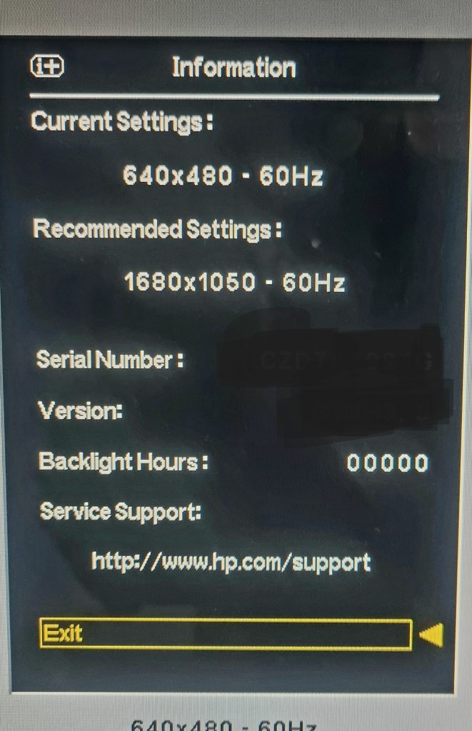
If you look at figure 9, you will see that the video card’s horizontal and vertical sync is working, as the monitor has correctly said that it is setup for 640 x 480, 60 Hz.
can I use a 25 MHz instead of 25.175 MHz?
There is another test that I would like to perform. Although the VGA specification calls for a clock frequency of 25.175 MHz, I would like to test if my circuit will still generate sync and blanking signals still within specification, when using a 25 MHz clock. Although you can buy 25.175 MHz crystal oscillators, 25 MHz ones are easier to find and this would add another option for anyone who wishes to build this but has struggled to find one. The reason why I think that this could still work is that there is some tolerance built into the VGA specification. VESA (an organisation that defines technical standards, including VGA) allows for a tolerance of 0.5%. This means that the lowest clock frequency should be 25.049125 MHz. Although this is above 25 MHz, it’s close enough that I think it’s worth trying!
conclusion
I have designed, built and tested a video card that has a visible range that conforms to the VGA specification of 640 x 480 pixels. This works on the standard clock of 25.175 MHz but will successfully work on a 25 MHz clock, even though it is technically not within the tolerance of the specification. The video card outputs colour via a DAC that consists of 2 parts red, 2 parts green and 2 parts blue, which means that this is a 64-colour (2 ^ 6) video card. This is known as 6-bit RGB.
If you would like to build my video card, then you can buy a PCB from my Tindie store: VIDEO CARD