Back to: Build a 6502 based computer
I want to add the ability to use a keyboard, so I can enter information into programs that are running. To do this I need to design and build a keyboard controller. This controller needs to provide two interfaces, one to the keyboard and one to the computer. I also need to write a driver (that will reside in the EEPROM) that translates the output from the keyboard (these are known as scan codes) and outputs the results to the VIA.
There are three aspects to consider with this goal, the physical connection, the protocols and the driver.
connection
There have been a number of implementations of keyboard connections and protocols. I want to make my computer work with PS/2 keyboards. Technically this means that my computer will also work with AT keyboards – even though they use different connectors, electrically they are the same! Also, technically some USB keyboards (with a modification to the connector) can be used! This is possible because SOME USB keyboards contain a multi-mode controller, which can be used to detect if a connection to PS/2 has been made. This exists because there was a period of time when both USB and PS/2 keyboards existed together and this allowed a USB keyboard to be connected to a computer with a PS/2 keyboard port, via an adaptor. However, this only works if the USB keyboard contains the multi-mode controller!
protocol
The PS/2 protocol consists of a serial frame of 11 bits. The 11 bits consist of a start bit, an 8-bit keycode, a parity bit and a stop bit. The 8-bit keycode represents the character that has been pressed. There is a problem, I’m only interested in the 8-bit keycode, I don’t need the other 3 bits! The way that I will handle this is in software, I will sample the 11 bits and discard the 3 bits that I don’t need, leaving me with the 8 bits that represent the character that has been pressed!
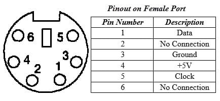
A PS/2 connector has 6 connections but only 4 are used. These are ground, 5V, clock and data. When a key is pressed, the 11-bit serial frame of data is sent over the data line. The clock line puts out a pulse for every bit sent over the data line.
The 8-bit keycode corresponds to a unique key. To begin with, I will work on A – Z and 0 – 9, as all other keys (shift, space, esc, caps lock etc) do not follow the pattern that the alphanumeric ones do! Table 1 shows the hexadecimal representation of each key. Each key actually has 2 keycodes. This is to distinguish between a key being pressed (key down) and the release of a key (key up). There are applications where it is important to be able to identify both a key down and a key up (such as games). To identify a key up, the key down code is used with F0 preceding it.
The 8-bit keycode is what I’m interested in. What I want to do is to read the 11-bit serial frame and strip the 8-bit keycode from it and discard the start bit, parity bit and stop bit.
| KEY | KEY DOWN | KEY UP |
|---|---|---|
| A | 1C | F0, 1C |
| B | 32 | F0, 32 |
| C | 21 | F0, 21 |
| D | 23 | F0, 23 |
| E | 24 | F0, 24 |
| F | 2B | F0, 2B |
| G | 34 | F0, 34 |
| H | 33 | F0, 33 |
| I | 43 | F0, 43 |
| J | 3B | F0, 3B |
| K | 42 | F0, 42 |
| L | 4B | F0, 4B |
| M | 3A | F0,3A |
| N | 31 | F0,31 |
| O | 44 | F0,44 |
| P | 4D | F0,4D |
| Q | 15 | F0,15 |
| R | 2D | F0,2D |
| S | 1B | F0,1B |
| T | 2C | F0,2C |
| U | 3C | F0,3C |
| V | 2A | F0,2A |
| W | 1D | F0,1D |
| X | 22 | F0,22 |
| Y | 35 | F0,35 |
| Z | 1A | F0,1A |
| 0 | 45 | F0,45 |
| 1 | 16 | F0,16 |
| 2 | 1E | F0,1E |
| 3 | 26 | F0,26 |
| 4 | 25 | F0,25 |
| 5 | 2E | F0,2E |
| 6 | 36 | F0,36 |
| 7 | 3D | F0,3D |
| 8 | 3E | F0,3E |
| 9 | 46 | F0,46 |
What I need to design and make is a controller to connect a ps/2 keyboard, that can communicate serial data to the computer. The controller allows the keyboard to talk to the computer, as it cannot do this directly. The controller will take care of the signal level and protocol details, as well as providing conversion, interpretation and handling of scan codes and commands. In software I will need to write a keyboard driver that takes the scan code, consults a lookup table to find which key had been pressed and then the computer can output that character or if it is a function key, act accordingly.
proof of concept
Before moving on to write the code for the computer that will reside in the EEPROM, I want to test the circuit and make sure that it is outputting the scan codes and only the 8-bit portion that I’m interested in. I plan on testing this by using an Arduino Uno and connecting the 8 bits to 8 of the digital pins. I will then write code to read the state of each pin. The code will take the 8 bits and convert it into a decimal number. It will then convert this decimal number into its hexadecimal equivalent. Then I will be able to press a key on the keyboard and check that the hexadecimal number corresponds to the scan codes.
Now that I have verified that the circuit is working, I will now work on making the equivalent program in assembly, so I can upload it to the EEPROM.
I need to take the 8 bit binary from the keyboard controller and connect it to the VIA.
I need to take the 8 bit binary value that has been fed to the VIA and compare it to values in a lookup table that contains a character map of all the alphanumeric keys.
Write an interrupt handler that interrupts the scan codes and prints out the letters that have been typed. We get an interrupt Read scan code and put it into a counter variable, which is what is being displayed on the screen:
inc_counter:
pha
lda PORTA
sta counter
pla
rti
Make a keyboard buffer for storing key presses. Then as the software reads the keys, it reads them out of the buffer, that way if more keys than the software can deal with are typed, it can be read into the buffer. I will give the buffer two pointers: a write pointer and a read pointer. So when you press a key, they get put in the buffer, specified by the write pointer and when the program reads from the buffer it will read at the offset specified by the read pointer. If the two pointers are the same, that means that everything from the buffer has been read. If the two buffers are different, then that means that there are some keys that have been pressed that are in the buffer that have not yet been read yet by the software. Set the location of the keyboard buffer in memory as 0200 through to 02FF, which gives 256 bytes in the keyboard buffer and because both the read and write pointers are 8-bit values, whenever either of them passes 255, they will wrap around to 0. Since a human cannot type more than 256 keystrokes before the program reads from the buffer, it will never be filled up! Therefore the circular buffer will work indefinitely!
The keyboard buffer is a location in memory that is used to store keystrokes before they are processed. This is known as typeahead. These can be stored here until the software is ready to read them.
The keyboard controller is an interface between the keyboard and the computer, it informs the computer when a key is pressed or released. When data from the keyboard arrives, the controller raises an interrupt to allow the CPU to handle the input.