Back to: Build a 6502 based computer
Now I would like to add an LCD to my computer, so that I can write programs that output characters.
I will be using the HD44780U. Note that this is not the model of the LCD module but actually the model of the LCD controller and driver! This means that you can use any LCD module that includes the HD44780U! The display that I want to use contains a HD44780U and can be used to display alphanumeric characters and symbols, on 2 lines of 8 characters. It can operate in either 4-bit or 8-bit mode and needs a voltage in the range of 3 – 11V.
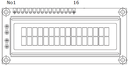
There are 16 pins to connect to the module, that require specific signals to make it work, see Figure 1.
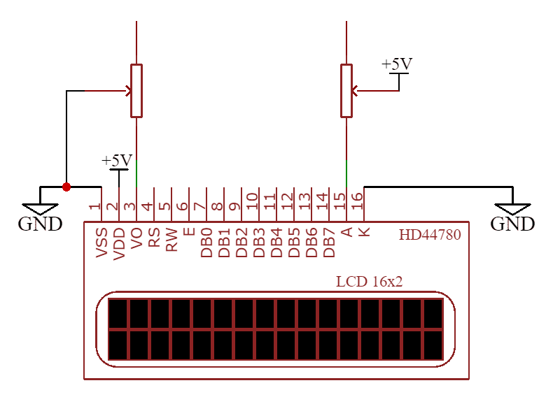
First I will connect the pins that supply power to the module: VSS (ground) and VDD (3 – 11V). I will use the regulated 5V supply to power the LCD module.
V0 is an analogue connection, for adjusting the contrast. I will connect this pin to ground, via a variable resistor, so I can fine-tune the contrast.
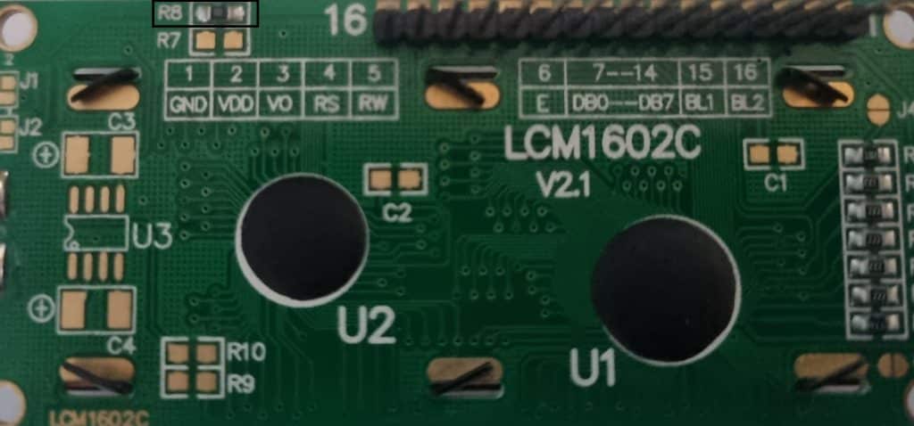
A and K are for the display’s backlight – A is for the anode and K is for the cathode. This can be connected directly to 5V because the LCD contains a current-limiting resistor, see R8 in figure 2. However, I will add a variable resistor so I can fine-tune the brightness.
Before I connect the LCD module to the computer I would like to check three things: that it is receiving power, that the backlight is on (and adjustable) and that the contrast can be adjusted. Being able to adjust the brightness and contrast means that it can accommodate different lighting situations.
I have wired up the LCD module as described and as shown in figure 3. Video 1 shows that everything is working.
Now I want to connect the data lines, so I can send data to the LCD. There are 8 data lines, D0 to D7. I will connect these to the data pins of the 6522.
Technically I could connect just 4 of the data pins! The LCD can be operated in either 4-bit or 8-bit mode. The benefit of the 4-bit mode is that it frees up 4 connections, which could be valuable in a computer. However, there is a trade-off in speed, as it will take longer to get data to the LCD, when compared with the 8-bit mode. Also, it requires adding extra code.
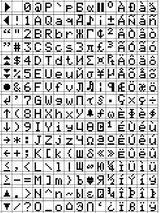
Figure 4 shows all of the characters and symbols that can be displayed.
There are 3 control signals that need connecting, RS, RW and E. Because the 6522 has 2 I/O ports, I can use the one that I am not using for the control signals.
We can send data through the data lines to either an instruction register or a data register. Which one is used is determined by the register select (RS) pin. If RS is low then data will go to the instruction register, such as initialising the display or clearing the display or moving the cursor around. If register select is high, then the data goes into the data register, such as sending characters to the screen.
The read-write pin (RW), such as reading what’s in the data register.
The E (enable) pin has to be high for reading or writing to take place.
With all of these pins connected, I now want to write a program to check that the LCD is working correctly.
The first thing that I want to do is to write a reset routine. Before the LCD module can be used, there is some setting up that needs to be performed. The 2 ports are going to be used as outputs, so I need to send instructions that make them outputs. I will do this for DDRB by loading 11111111 into the accumulator (LDA) and then storing that value at address $6002. I will then do the same for DDRA, except the address will be $6003.
INERTNAL RESET
There is no need to perform a reset when you apply power to the LCD module, as it contains circuitry to perform an internal reset.
lda #%11111111 ; set all PORTB pins to output
sta $6002


lda #%11111111 set all PORTA pins to output
sta $6003
Next, I need to set the mode (4 or 8-bit), how many lines to use (1 or 2) and which font (5 x 8).
lda #%00111000 set to 8-bit mode, 2-line display, 5 x 8 font
sta PORTB
lda #0
sta PORTAlda #E
sta PORTAlda #0
sta PORTATo send alphanumeric characters and symbols, this information needs to be presented in ASCII. ‘I’ in ASCII is 01001001 (Figure 4). Therefore, if I want to print ‘I’, I can perform an lda #01001001.
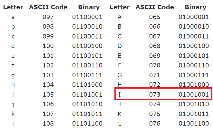
However, this is not necessary. Instead, I can write lda #”I”. This works because the assembler will convert the ‘I’ to ASCII!
lda #"I"
sta PORTB
lda #RS         ; Set RS; Clear RW/E bits
sta PORTA
lda #(RS | E)   ; Set E bit to send instruction
sta PORTA
lda #RS         ; Clear E bits
sta PORTA
Here is the complete program:
PORTB = $6000
PORTA = $6001
DDRB = $6002
DDRA = $6003

E  = %10000000
RW = %01000000
RS = %00100000

  .org $8000

reset:
  lda #%11111111 ; set all pins on port B to output
  sta DDRB

  lda #%11111111 ; set all pins on port A to output
  sta DDRA

  lda #%00111000 ; set 8-bit mode; 2-line display; 5x8 font
  sta PORTB
  lda #0         ; clear RS/RW/E bits
  sta PORTA
  lda #E         ; set E bit to send instruction
  sta PORTA
  lda #0         ; clear RS/RW/E bits
  sta PORTA

  lda #%00001110 ; display on; cursor on; blink off
  sta PORTB
  lda #0         ; clear RS/RW/E bits
  sta PORTA
  lda #E         ; set E bit to send instruction
  sta PORTA
  lda #0         ; clear RS/RW/E bits
  sta PORTA

  lda #%00000110 ; increment and shift cursor; don't shift display
  sta PORTB
  lda #0         ; clear RS/RW/E bits
  sta PORTA
  lda #E         ; set E bit to send instruction
  sta PORTA
  lda #0         ; clear RS/RW/E bits
  sta PORTA

  lda #"I"
  sta PORTB
  lda #RS         ; Set RS; Clear RW/E bits
  sta PORTA
  lda #(RS | E)   ; Set E bit to send instruction
  sta PORTA
  lda #RS         ; Clear E bits
  sta PORTA

  lda #"'"
  sta PORTB
  lda #RS         ; Set RS; Clear RW/E bits
  sta PORTA
  lda #(RS | E)   ; Set E bit to send instruction
  sta PORTA
  lda #RS         ; Clear E bits
  sta PORTA


  lda #"M"
  sta PORTB
  lda #RS         ; Set RS; Clear RW/E bits
  sta PORTA
  lda #(RS | E)   ; Set E bit to send instruction
  sta PORTA
  lda #RS         ; Clear E bits
  sta PORTA

  lda #" "
  sta PORTB
  lda #RS         ; Set RS; Clear RW/E bits
  sta PORTA
  lda #(RS | E)   ; Set E bit to send instruction
  sta PORTA
  lda #RS         ; Clear E bits
  sta PORTA

  lda #"A"
  sta PORTB
  lda #RS         ; Set RS; Clear RW/E bits
  sta PORTA
  lda #(RS | E)   ; Set E bit to send instruction
  sta PORTA
  lda #RS         ; Clear E bits
  sta PORTA

  lda #"L"
  sta PORTB
  lda #RS         ; Set RS; Clear RW/E bits
  sta PORTA
  lda #(RS | E)   ; Set E bit to send instruction
  sta PORTA
  lda #RS         ; Clear E bits
  sta PORTA

  lda #"I"
  sta PORTB
  lda #RS         ; Set RS; Clear RW/E bits
  sta PORTA
  lda #(RS | E)   ; Set E bit to send instruction
  sta PORTA
  lda #RS         ; Clear E bits
  sta PORTA

  lda #"V"
  sta PORTB
  lda #RS         ; Set RS; Clear RW/E bits
  sta PORTA
  lda #(RS | E)   ; Set E bit to send instruction
  sta PORTA
  lda #RS         ; Clear E bits
  sta PORTA

  lda #"E"
  sta PORTB
  lda #RS         ; Set RS; Clear RW/E bits
  sta PORTA
  lda #(RS | E)   ; Set E bit to send instruction
  sta PORTA
  lda #RS         ; Clear E bits
  sta PORTA


loop:
  jmp loop

  .org $fffc
  .word reset
  .word $0000