Back to: Build a 6502 based computer
Unused input pins
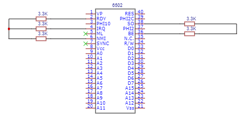
The first thing that I want to do is to connect the pins of the 6502 that I will not be using. Often there are pins on ICs that you will not use. With unused pins that are inputs, you should not leave them unconnected – this is because they can ‘float’, causing undesirable results.
There are 5 input pins that I will not be using at the moment. Rather than connect them directly to +5V, I will connect them via a 3.3K resistor: BE, SO, RDY, IRQ and NMI. Later on, I plan on using IRQ, BE and RDY.
BE is the bus enable pin and is used to control the buses externally. This pin only exists on WDC’s 65C02 and isn’t found on any other manufacturers iterations.
SO is the set overflow pin. This is a pin that was very rarely used and it’s recommended that you don’t use it in modern designs.
RDY is the ready pin, used for wait states and single-stepping. The 6502 used to have an internal resistor on the RDY pin but WDC removed it. I recommend that whatever version you use, add a pull-up resistor. Not only will this stop the pin from floating, but it could also potentially protect the 6502 from damage! The RDY pin on WDC’s 6502 is bidirectional and connecting it directly to +5V could cause damage.
IRQ is the interrupt request pin. This pin is used to start an interrupt sequence. This is maskable, which means that it will not happen straight away, if there is something that has to be finished first.
NMI is the non-maskable interrupt pin. This pin is used to start an interrupt sequence. This is non-maskable, which means that it will happen as soon as possible.
Unused output pins
There are also two output pins, SYNCH and ML, that I will not be using. These are output pins and can be left unconnected, as, unlike inputs, they don’t have the potential to cause problems!
SYNCH is the synchronise pin. This is used to identify when the 6502 is fetching an OpCode.
ML is the memory lock pin. This is used when you have a design that uses more than one 6502. This pin is only found on the 6502 from WDC.
Summary
I have connected pull-up resistors to input pins that I will not be using, to stop them from floating and to protect the RDY pin from potential damage. Figure 1 shows the circuit so far.