Back to: Build a 6502 based computer
Next, I need to power the 6502. The 6502 can be powered from any voltage in the range of 1.8 to 5V. I will be using 5V, as this will be suitable for other ICs that I will be using. Pin 8 is connected to the positive rail and pin 21 is connected to the negative rail.
I will use a voltage regulator to allow for a flexible input voltage range and to make sure that the output remains at 5V. I will be using a 7805, which will allow me to use an input voltage in the range of 7 – 35V. I also want to use the 7805 because it was introduced in 1972, meeting my criteria of being of the era. The 7805 can be used with currents up to 1.5A, which should be fine, as I don’t imagine that the current requirements of the computer to be anywhere near this. The 7805 can be used at higher currents, if a suitable heat sink is used. The 7805 is very robust, it has built-in protection against overheating and short circuits.
Connections
Figure 1 shows the connections for the 7805. There is a ground that is common to the input and output voltage, a connection for the input +V and output +V.

The voltage regulator will work without any additional components, providing a fixed 5V. However, there will be some parasitic inductance, which can cause problems with digital circuitry. Therefore, to improve stability and to reduce inductance, I will add 2 ceramic capacitors, see figure 2. These should be as close as possible to the terminals as possible. The fixed 5V will then have less ripple and provide the computer with a more reliable 5V. The reason why I will use ceramic capacitors and not electrolytic is that they will react quicker to any ripple that is present.

There are two more components that I would like to add to the circuit – diodes. I will connect one of the diodes in the reverse bias configuration., figure 3. The reason for adding a reverse-biased diode is to prevent damage to the 7805 in a situation where a charge stored in the output capacitor sends a reverse voltage to the voltage regulator. The second diode is to protect my computer if the power supply is connected the wrong way around. This could happen because power supplies that are terminated with a barrel jack can be centre-positive or centre-negative! Centre-positive is more common and how I have designed my circuit to work. If, however, a centre-negative power supply was connected, my computer would not be damaged, as the diode would be reverse-biased. I have used two 1N4001 diodes, which have a maximum rated current of 1A. I don’t imagine the computer drawing more than 1A, so this should not be a problem!

Minimum voltage
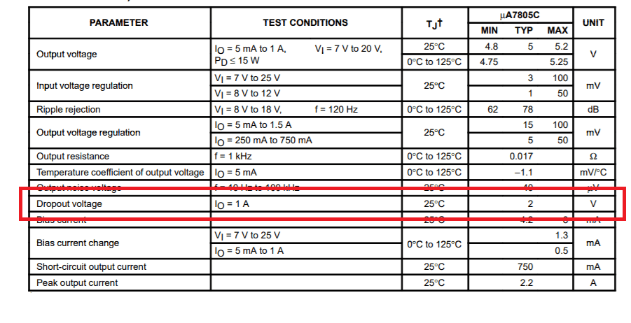
7V is the minimum voltage that can be placed at the input of the 7805, to make sure that the output is always at 5V. This is because of the dropout voltage of the 7805! Dropout voltage is a feature of linear voltage regulators, of which the 7805 is one. One of the disadvantages of linear voltage regulators is that they always need to be supplied with a voltage higher than the voltage that they need to output. How much is known as the dropout voltage. If you look at table 1, you will see a section of the 7805 datasheet that specifies this to be 2V.
This means that the minimum input voltage = output voltage + dropout voltage. Therefore 5V + 2V. However, there is more to consider. There is a side-effect of using a diode! The diode will have a voltage drop of 0.7V! Therefore. the minimum input voltage = output voltage + voltage regulator dropout voltage + diode voltage drop, 5V + 2V + 0.7V = 7.7V. Therefore the minimum voltage that can be used is 7.7V. In reality, the voltage drop of the diode is approximate. Therefore any voltage of 7.7V or above is fine.
Maximum voltage
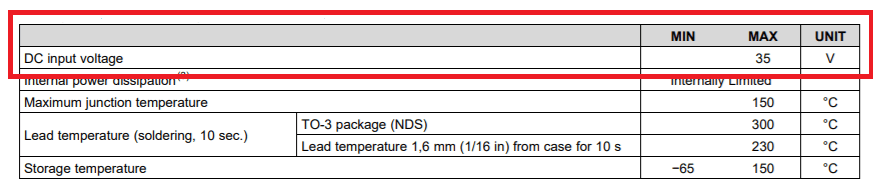
Figure 4 shows a section of the datasheet of the 7805. From this it can be seen that 35V is the maximum voltage that I could use to power my computer.
Wasted energy
This ‘wasted’ voltage is dissipated as heat. Therefore, the higher the difference between the input voltage and the output voltage, the greater the wasted energy and the more heat that is dissipated. This can be reduced by using an input voltage that is close to the output voltage + the dropout voltages.
Assuming a current of 1A, take a look at these two calculations:
(7.7V – 5V) x 1A = 2.7W (from supplying the minimum voltage).
(35V – 5V) x 1A = 30W (from supplying the maximum voltage).
This shows that with an input voltage of 7.7V, 2.7W of power is being wasted. However, with an input voltage of 35V the wastage is over 10 times greater!
Therefore, to minimise wasted energy, I would like to use a power supply as close to 7.7V as possible but in reality, a voltage of 7.7 – 35V will work.
Summary
I have built a circuit to clean up and supply 5V from any power supply that is in the range of 7.7 – 35V. Figure 5 shows the circuit so far.
