Back to: Build a 6502 based computer
Now that I have connected the pins that I will be using, the input pins that I will not be using and the power supply pins, I would like to test if the circuit so far is working and that my 6502 works. There are a number of ways that I could do this, the way that I will do it is to place LEDs (with protection resistors) on the 16 address lines, see Figure 1. With power applied, the 6502 should run and LEDs should light up, showing that the 6502 is accessing different address lines.

The test was successful and demonstrates that the circuit and the 6502 is working. However, it doesn’t demonstrate anything further! The addresses that are being displayed are meaningless. What would be good would be to place the 6502 into a known state and run a program.
NOP
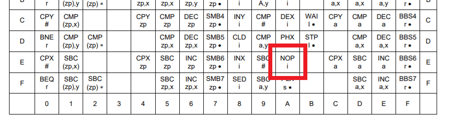
What I will do is create a hard-wired program! I will achieve this by using an OpCode named NOP. OpCode is short for Operation Code. An OpCode is an instruction that specifies an operation to be performed. NOP stands for No OPeration. NOP is an OpCode that does nothing, except for incrementing the program counter. Looking at table 1, you will see a section of the 6502 datasheet named OpCode matrix. This contains all of the different OpCodes that the 6502 can perform. If you go to row E and across to the column with A, you will see NOP. This means that if EA is presented to the data bus, the 6502 will run the NOP. Also, if you look under NOP, you will see an i. The i denotes that a NOP takes two clock cycles to complete.
EA is a hexadecimal number, we need its binary equivalent to know which values to place onto the data bus. E = 1110 and A = 1010. Therefore EA is equal to 11101010 in binary. I will place 11101010 onto the data bus by connecting pins that need to see a 0 to ground and those that need to see a 1 to 5v, see figure 2. I can then monitor the 16 address lines by watching the LEDs. The 6502 running the NOP should cause the program counter to increment each time and the address to increase. What should be seen is the address on the address bus being incremented in binary.

Tips
When I am building a circuit that uses a large number of resistors, I use a resistor array. The advantages of these are that they contain one common pin, reducing wiring and they come in many different sizes.
Summary
I have tested the 6502 and proved that it is working, by watching LEDs connected to the address change on the address bus. I have created a hard-wired program using resistors that corresponds to the OpCode NOP. I was able to see the address bus increment, by watching the LEDs connected to the address bus.
If you would like to buy a PCB of a NOP generator that I have created, you can do so at my Tindie store: https://www.tindie.com/products/6502/nop-generator-test-your-6502/