Back to: Build a 6502 based computer
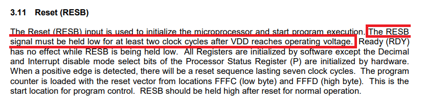
When the computer is switched on, it’s important that all clocked ICs start in a known state. So far there is the 6502 that is clocked but there will be others, as the computer is expanded. To make sure that the clocked ICs are in a known state, we need to reset them. Looking at the datasheet (figure 1) of the 6502 we can see its specific requirements. RESET (pin 40) needs to be driven low for a minimum of two clock cycles, after VDD (pin 8) reaches the operating voltage. RESET should then be returned to +V.
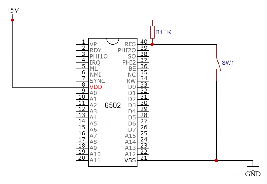
One way (figure 2) of achieving this would be to connect a switch between the RESET pin and ground and a pull-up resistor between the RESET pin and +5V. The RESET pin is active-low, so using a pull-up resistor will keep the RESET pin at +5V, until the switch is pressed, bringing it low. With a 1 MHz clock, two clock cycles is 2 millionths of a second, which will easily be met in this setup, as even the shortest press of the switch would result in many clock cycles passing!
Although this circuit will reset the 6502, it could cause problems, due to the nature of switch bounce. Switch bounce is a problem caused by the contacts of switches making contact multiple times before settling down. Adding a capacitor across the switch can help to clean things up but it’s not a good long-term solution. To neutralise this problem I will need to add a switch debouncer.
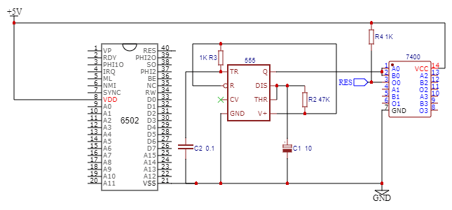
There are many ways of making a switch debouncer, the way that I’m going to do it is by using a 555 IC. The 555 is a very popular timer IC that can be configured in different ways (timers, pulse generators, oscillators etc). The 555 was designed in 1971, so meets my criteria of being from the era. Some of the alternatives for switch debouncers are not the most reliable methods, with a 555 a much more stable and reliable one can be designed. As well as two resistors and two capacitors, there is another component that is required – an inverter. This is because the output will be high and the 6502 RESET pin is active LOW. I could use a 7404, which contains 6 inverters but instead I have chosen a 7400, which contains 4 NAND gates. The reason for this is that I anticipate needing other logic gates in my computer. The NAND gate is known as a universal gate, meaning that all other gates can be made from it! I will configure the 555 to be a monostable multivibrator. A monostable multivibrator has only one state that is stable, the other state is temporary. This is exactly what we want, a temporary change to the logic level at the reset pin and then a return to its previous level. With the inverter on the output of the 555, when the computer is turned on, the 555 output will be a logic 1, meaning a logic 0 at the output of the inverter. These levels will then be reversed.
The 6502 is now being correctly reset but there is an improvement that I would like to make. Rather then turning on the computer and then pressing the reset button, I would like to make the computer reset itself when it is powered on! This is known as power on reset. The way that I plan on doing this is by using a further 555 wired as a monostable multivibrator. A monostable multivibrator is a one-shot timer, the output changes after a predetermined amount of time. This way I can wire this circuit to apply a pulse to the reset line, instead of the switch needing to be pressed!
When the 6502 is reset, there is a reset sequence that takes place, which is loaded from FFFC and FFFD. This reset sequence lasts for seven clock cycles and after this, the computer will be usable.
As more components are added to the computer, there will be other components that need to be reset into a known state when the computer is started. I will be able to reset these components by connecting them to this circuitry.
Summary
I have added circuitry that resets the 6502, ensuring that it starts in a stable and known state. As more components are added to the computer, there will be other components that need to be reset into a known state when the computer is started. I will be able to reset these components by connecting them to this circuitry. Figure 4 shows the circuit so far.
