Back to: Build a 6502 based computer
Why is a clock needed?
The function of the clock is to regulate the speed at which the 6502 executes instructions, as well as synchronising various components – to make sure that they are ‘in time’.
What speed?
The speed that the clock should be run at is dependent on a number of factors, including:
- The version of 6502 that I use
For the reasons mentioned previously, I will be using the 14 MHz version of the 65C02. Therefore, the fastest that I can make the clock is 14 MHz – in theory. A fun extension to this project would be to overclock the 6502 and see its true limit! - What I will use the computer for
I will be using the computer for a variety of tasks, this will be a general-purpose computer. - Limitations set by other ICs and components used
It’s possible that the speed will be lower than 14 MHz, as there are propagation delays and other clock speeds to consider when I begin to add further parts!
Methods of clock generation
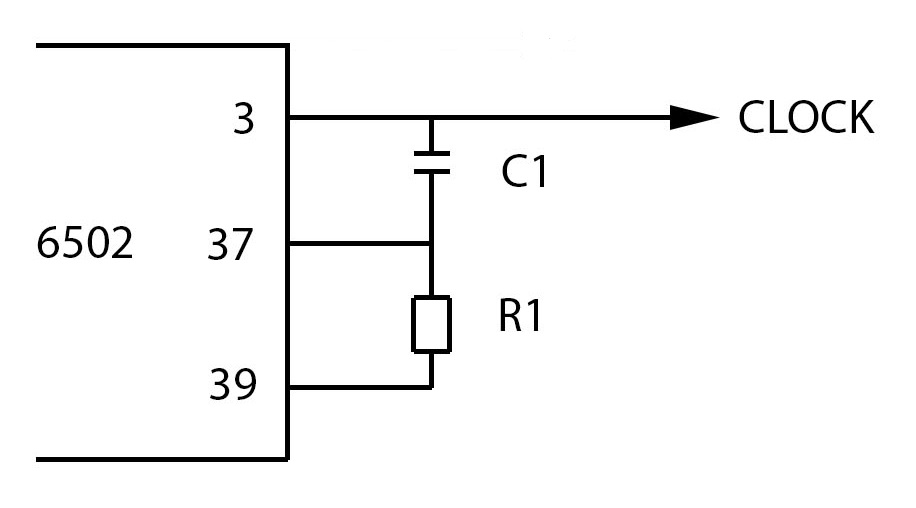
There are many ways to generate a clock signal. Before discussing some of these, I think that it is important to define what the clock signal should look like and to talk about how a clock pulse was generated with the original 6502 vs how it should be now! I want a clock signal that is a square wave, with a 50% duty-cycle. All forms of 6502 have 3 clock pins. These are: phase 2 in (pin 37), phase 2 out (pin 39) and phase 1 out (pin 3). The original method of generating the clock signal used all of these connections. There is a better way, which is to only use the phase in (pin 37) connection. The reasoning for this will become apparent as I demonstrate different methods of generating the clock signal.
Internal oscillator
You can actually generate a clock signal by connecting just a resistor and capacitor, as shown in Figure 1. This is because all 6502s contain an internal oscillator! However, I would expect the resistor-capacitor solution to not be the most stable solution and could be affected by external factors, such as temperature fluctuation and component tolerances. Also, WDC does not recommend relying on the internal oscillator for their 6502.
555
Another approach is to use a 555, operating in astable mode. It will be interesting to see how reliable this is for my needs. I imagine that it may work ok at the lower end but as I increase the frequency, reliability will drop. Since its creation (in 1972), there have been more than 20 variants of the 555! The fastest variant can theoretically be used for frequencies up to 5 MHz. However, this will depend on different factors and whether it would be good enough for the 6502 would need to be tested!
A square-wave, that has a 50% duty-cycle, is achievable with a 555. I will use potentiometers for R1 and R2, to allow me to alter the frequency and the duty-cycle. However, this is another reason why an oscillator will be a better choice, as they are more stable. The duty cycle of a 555 can drift.
An improvement can be made to this circuit by adding a capacitor between pin 5 and ground. Pin 5 is the control pin and by adding a capacitor, it helps to filter noise that may be present. If you were using a 555 to flash an LED, then you could do without it but because I am using it to create a clock signal, I want it to be as clean as possible.
Electrolytic capacitors have a wide tolerance. I could use a capacitor with a narrower tolerance but their cost is far greater and I could buy a crystal oscillator for the same price!
Crystal
Crystals can be used to provide a stable clock signal but they are not as reliable as crystal oscillators.
Crystal oscillator
The final and what I expect to be the best solution, is an oscillator. The reason that I expect an oscillator to be the most reliable solution is that they are stable and less susceptible to EMI.
Figure 2 shows the computer so far. I have the CPU connected, along with the clock.
Single stepping
When testing the computer it is useful to be able to stop the clock and single-step it, allowing you to see what is on the buses. Although I want to use a crystal oscillator in the final design, I will use a 555 to make a clock signal that can be single-stepped!
Final choice
I don’t actually have a single choice – I have two choices! Using the static 6502 means that you don’t need a continuous clock to keep the contents. This means that it is possible to stop the clock and look at what is happening and also to single-step through the processes. The crystal oscillator is the most stable option and therefore I would like to use that as the clock for when the computer is operated ‘normally’. However, I could use a 555 operating in astable mode as a clock that could be used to run the computer at slower speeds and a 555 operating in monostable to single-step. Two 555 ICs would be fine but there is an optimisation that could be made. There is a 556, that contains two 555 ICs in it. This will reduce the space taken up by two 555 ICs and only need one power rail. The 556 can be operated in the voltage range of 4.5V and 16V, so it will be fine on 5V. Also, the 556 came out in the 70s, so this fits the era criteria. My idea is that there will be three switches. One to have a switch that allows you to switch between the crystal oscillator and the 556. There will also be a switch that you then choose between the astable free-running or single-stepping. There will then be a push-button switch for single-stepping.
Summary
I have two clock circuits: one using a 556 timer IC and the other using a crystal oscillator. I will use the one that uses the 556 for testing purposes, as I will be able to control the frequency and duty cycle. I like the idea of using a 556 in my computer as it was available at the time of the 6502! Figure 2 shows the circuit so far.
